by Stefan Speiser
Hello everyone, my name is Stefan Speiser. I am a graduated Bachelor Student from the University of Applied Sciences (UAS) Technikum Wien in Vienna, Austria. I will present today my bachelor thesis in which I have worked with ReconstructMe.
The goal of the thesis was to create a booth for trade fairs and open days at the UAS Technikum Wien. At that booth a 3D-Scan of any willing visitor will be created, modified and then shown on a 3D-Monitor, so that the visitor can view him/herself in 3D. To reduce the needed time for the whole scanning-, modifying- and output process, a script capable of automating mentioned processes was created.
The booth was made as a marketing strategy of the UAS, in order to attract even more students than before by demonstrating how interesting technology can be.
This picture shows an early development stage of the booth with a functioning version of the script and all programs working as they should. On the left you can see the 3D-Monitor, next to it the control monitor where ReconstructMe runs and on the right is the Kinect System. Just barely visible on the bottom is a rotating chair.
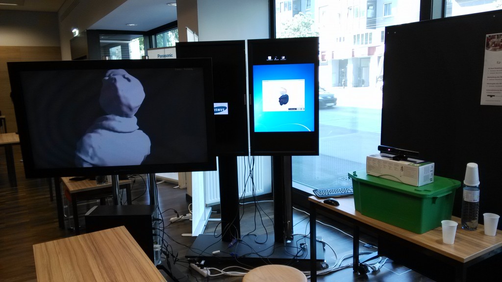
Early development stage of the booth
To explain how I achieved this result, I would like to first write about the used hard- and software and afterwards explain the automationscript in detail.
Microsoft Kinect
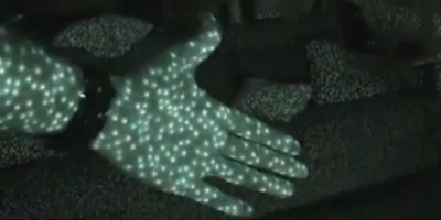
To get the visual information needed for the 3D-Scan a Microsoft Kinect System was used. The person to be scanned sits in front of the Kinect System on a rotating chair. The built-in infrared projector emits a pattern of dots which covers the person standing in front of the Kinect Sensor and the rest of the room. These dots get recorded by the infrared camera and the Kinect System can calculate a depth image with this information.
An RGB camera recording at a resolution of 640×480 pixel and a frame rate of 30Hz grabs the color information of the scene in front of the Kinect System.

IR-Pattern from infrared projector (Source: MSDN, 2011)
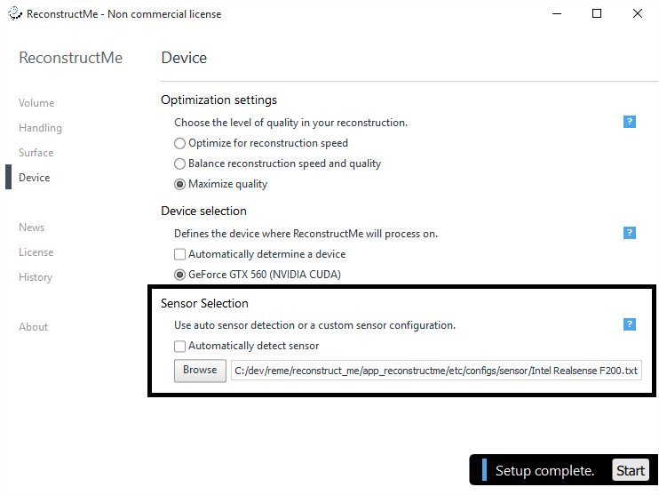
ReconstructMe
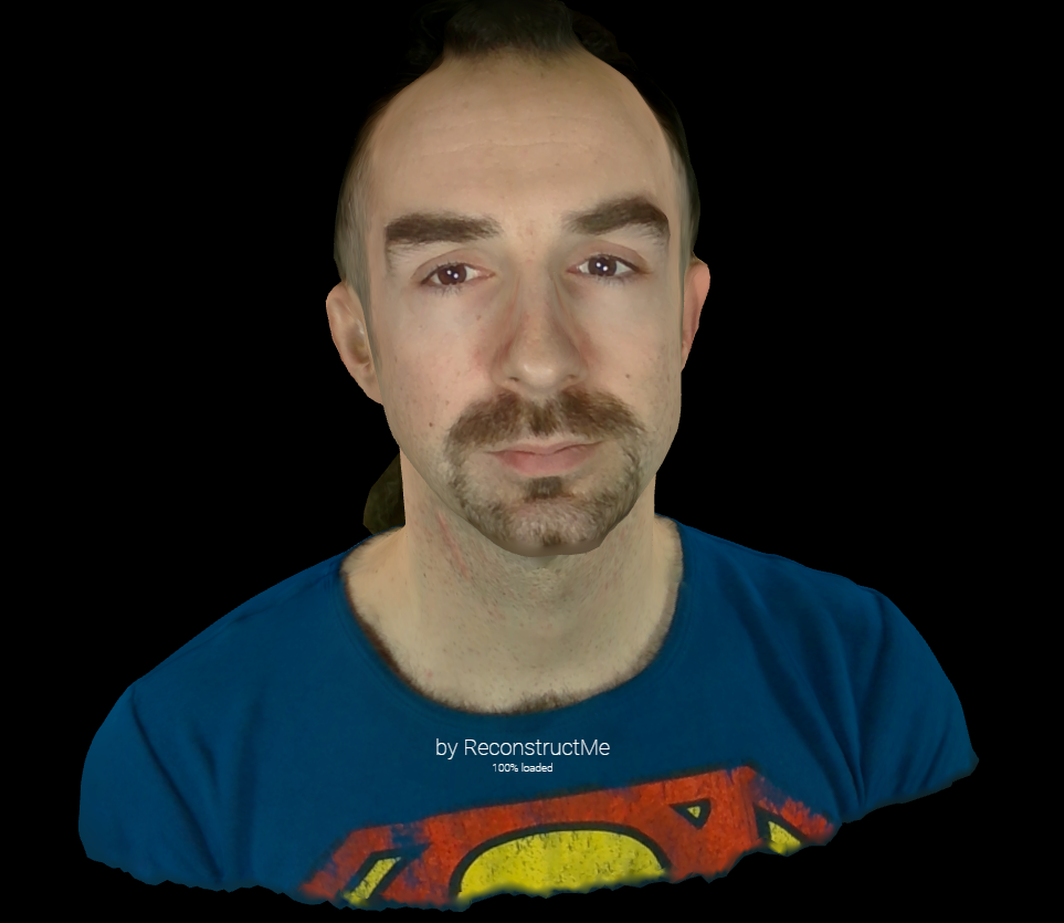
Both the depth image and color image information from the Kinect System is used by ReconstructMe. Since ReconstructMe offers native plug-and-play compatibility with the Kinect System, making scans was a breeze. The built-in 3D-Selfie function of ReconstructMe was the perfect fit for my project. It detects automatically when the person in front of the Kinect System rotates a full 360 degrees and stops recording the scan. During the processing phase, ReconstructMe stitches all holes in the mesh, shrinks the 3D-Scan and slices the upper body, so that if you would like to 3D-Print your scan, you could just save it and would be ready to 3D-Print it. (More information about the 3D-Selfie function can be found here: http://reconstructme.net/2014/04/24/reconstructme-2-1-introduces-selfie-3d/)
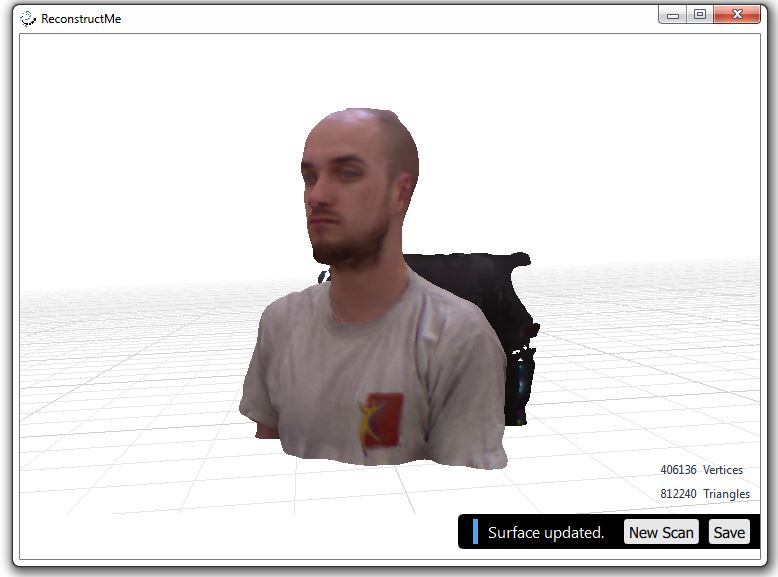
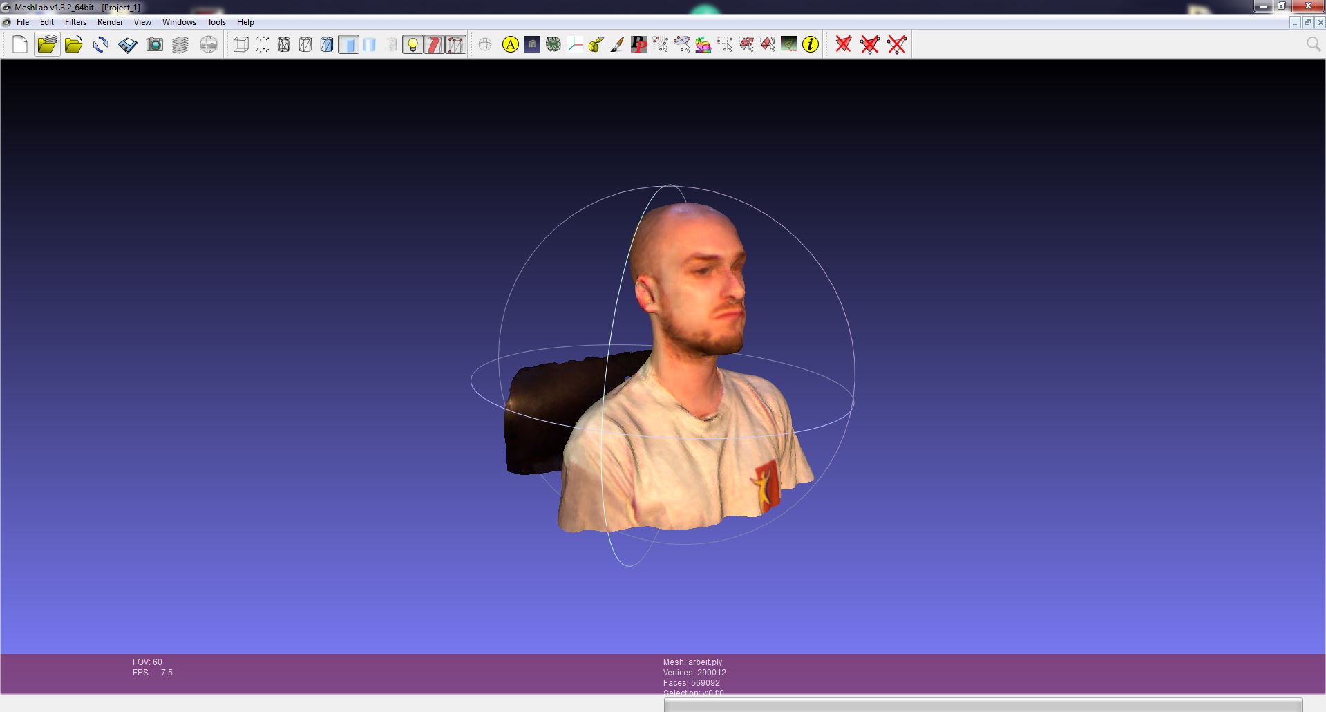
3D-Selfie scan after ReconstructMe processing
Meshlab/MeshlabServer
Meshlab is an open source program which allows you to process and edit meshes. A mesh is collection of for example triangles which build a three-dimensional structure. Available is either the program version with a GUI or MeshlabServer. The special thing about MeshlabServer is the possibility to create a script with all the filters you would like to apply to your mesh and then start this script via the command console. For the sake of automation this approach is of course the favorable.
The filters used in my script are rotating and increasing the 3D-Scan from ReconstructMe to make it better visible on the 3D-Monitor and another filter is reducing the amount of triangles in the mesh by half. The quality reduction is almost not visible, but the file size and therefor the time needed to save the modified mesh is also reduced by half.
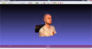
Meshlab
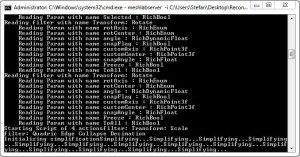
Meshlabserver
Tridelity MV5500 3D-Monitor
The modified 3D-Scan is shown to the visitor on an autostereoscopic 3D-Monitor. What is autostereoscopy you might ask? It’s a technology which enables the viewer to see a three-dimensional picture without the need for 3D-Glasses or similar equipment.
This effect is achieved with a parallax barrier, a barrier mounted in front of the LCD panel which only allows the viewer to see one picture for the left eye and one for the right eye. By chopping the 3D-Scan into small slightly shifted vertical lines, the brain stitches these pictures together and makes you see a 3D-View. This effect works best at a specified distance and since the monitor supports MultiView, up to 5 people can view the 3D-Scan at the same time from different angles. Depending on the angle to the monitor, the viewer sees the 3D-Scan more from the front or from the side.
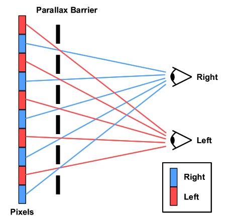
Parallax Barrier schematic (Source: Muchadoaboutstuff, 2013)
AutoHotKey & Gulover´s Macro Creator
To automate keyboard entries and mouse clicks in the used programs, AutoHotKey was the tool of choice. It lets you automate every thinkable action in the Windows OS and every program running in it. It features IF/ELSE, Loops, a PictureSearch where you can search for a specific detail on the screen and if it’s found fire another function and many other tasks.
Gulover´s Macro Creator is a freeware program which offers a GUI for all functions and tasks of AutoHotKey. This makes working with and programming scripts in AutoHotKey much more time efficient and easier.
This was the description of the utilized hard- and software, now let me explain the automation script in detail.
The automationscript
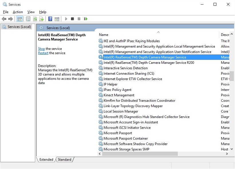
The script first starts ReconstructMe and the Tridelity Software which loads the last saved 3D-Scan and outputs it on the 3D-Monitor. Then via PictureSearch ReconstructMe is scanned for an error message which appears when the Kinect Sensor is not recognized. If the error appears, the user is asked via a prompt to solve the problem with instructions given.
Next a 3D-Selfie scan is started and when finished the user and the visitor are asked if they like the result or if another scan should be started. If they are content, the scan gets saved and overwrites the last saved scan.
Now the visitor gets asked if he would like to save the scan in an extra folder. If this is wished for, the visitor gets to enter his name which is then saved with the current date added into a specific extra folder. The visitor could now copy the scan on an USB-Stick and take it home and modify it or directly print it with a 3D-Printer.
The scan is now getting modified by the Meshlab script running in MeshlabServer. After the filters are applied the now modified scan gets saved as a .obj file which in the next step can be opened by the Tridelity 3D-Monitor software. This software outputs the 3D-Scan and rotates it so that the visitor can view himself in all different angles. As you can see in the pictures, the 3D-Scan created in ReconstructMe is in color while the output on the 3D-Monitor is only in shades of grey. This is because the 3D-Monitor can only play back .obj files which are unable to store color information. ReconstructMe on the other hand offers four possible output file formats! (.ply, .stl, .obj, .mtl)
After a defined time the user gets asked if he would like to stop the script which would stop all running programs and then itself or if another scan is wanted in which case the script jumps back to the 3D-Scan routine and starts all over.
Thanks to a sponsored license for ReconstructMe which lowers the processing time after the completion of the scan by forty seconds, one complete pass of the script from the start of the 3D-Scan to the final output on the 3D-Monitor takes two minutes and twenty seconds. Definitely a time visitors are willing to wait and ask questions while their scan is being prepared for their viewing pleasure.
I would like to take this opportunity to once more thank the whole ReconstructMe Team, especially Mr. Rooker, and my UAF bachelor thesis supervisor FH-Prof. Dr. Kubinger for their support and valuable input.


