by Daniel Constantin
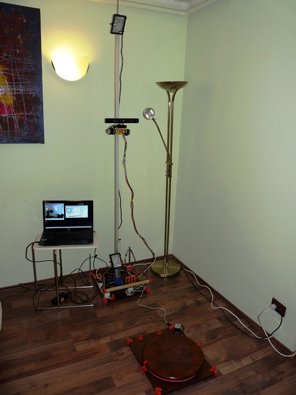
Scanoman ready for action
When I started the Scanoman project early this year, the following main requirements were considered:
- Very affordable – for anyone who would like to have/build one;
- Easily doable – by anyone who has minimal knowledge, experience and tools;
- 3D printable – for as many parts as possible;
- Lightweight and portable – so that one can take it here and there;
- Simply usable – by anyone having some technical common sense.
At the time, there was (and still is) little information available about building a full body scanner in a DIY style. Therefore, I decided the design would have to become open source so that anyone could get inspired and make one.
Professional studios opted for multiple cameras taking snapshots of the subject from various angles and then compiling the data into a 3D model. This was obviously not an option for the project.
The hobbyist strategy was to use an inexpensive sensor, normally dedicated to game consoles, mount it on a pole, and have the subject being scanned when standing on a rotating turntable in front of the sensor.
The later appeared to be a reasonable approach for my purpose.
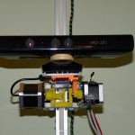
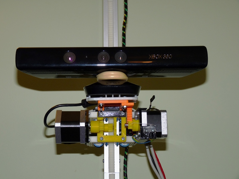
Microsoft Kinect for XBOX sensor mounted on Scanoman
Microsoft Kinect for XBOX was the sensor of choice. It was the cheapest available and I could buy it from a general electronic equipment store, which very well complied with the requirements. I was aware that this would be at the cost of lower quality, since the senzor resolution and accuracy are very, very basic, but was a good starting point.
The long connection cable was an advantage. Since the sensor would have to go up and down on the pole, having a continuous cable was a plus.
The sensor is mounted on a slider that is driven by a NEMA 17 stepper motor through a reduction gearing, which pinion is running on a rack along the vertical pole. Using a rack was a simple way to solve the requirement of having the pole composed by individual segments, so it can be easily assembled and disassembled.
The sensor could also be tilted. I didn’t find a quick and easy way to use the internal motor of the senzor, so I used yet another stepper motor mounted on the slider. I discovered later on that you do not actually need too much this function.
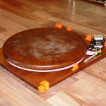
40 cm turntable driven by a NEMA 17 stepper motor
The turntable construction required to solving many engineering issues.
After considering various alternatives, I went for the one that could be built from easy to find parts. It uses a round worktop that I found in the hardware store in 40, 60 and 80 cm diameter. I took the smallest one, which would suffice in most cases for single person scanning, and mount eight 626 bearings underside, so it could spin around a central axis. While each bearing would have to support more that 10 kg each, I placed a 1 mm steel sheet on top of the base plate (which is a 40 x 50 x 18 cm hard wood board).
The most challenging part was to drive the turntable. After many trials, I came to the optimal configuration in respect to speed, power and… cost. Using a simple NEMA 17 stepper motor, a reduction gearing and a 300-tooth “circular rack” was enough to obtain a full rotation of an 160 kg load in 20 seconds!
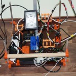
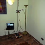
Main plate with pole mounting, controller, power and wiring
Having the sensor sliding along a 2.5 m height pole made from aluminum square tube (this was easier to found and cheaper than T-slot bars), cut in 5 segments, and the turntable easily rotating with one person standing on it have solved most of the construction issues.
A second hard wood board was used to mount the pole, the power supply, the controller, an USB hub and all the mountings used to hold parts of the scanner while disassembled.
Scanoman uses a controller designed for 3D printers, as it has to drive 3 stepper motors, sense 2 endstops, and also turn on and off the supplementary spotlights. And software-wise, it is controlled through the very well known (in the 3D printing reprap world) application called Pronterface. This was once again a proof that 3D scanning and 3D printing go hand in hand!
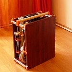
Scanoman packed and ready to go
As intended, Scanoman is portable.
It could be easily (dis)assembled in a quarter of an hour, using just a small screwdriver to fix the pole segments.
I have to admit that this version is not so light as I would liked too, weighting some 15 kg! Good news is that I identified means by which the total weight could be reduced by half!
Scanoman already traveled in Bucharest and is expecting more opportunities to do his job, which is, no wonder, to scan people. While some people might be happy to come to a scanning studio, others will prefer to being scanned at home. Or you can take it with you when going to a party and scan the participants!

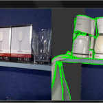
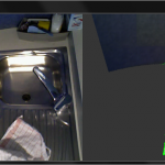
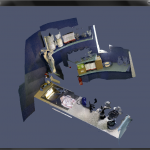
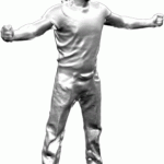
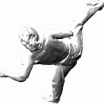
3D selfie of Vali
When it came to 3D scanning software the choice was not less than obvious: ReconstructMe!
It is by far the most user-friendly, rapidly evolving and almost free 3D scanning application.
ReMe does the job very well and fast. And it’s also fashionable. Want to have a 3D selfie? Nothing simpler, you get a ready to be printed bust model of yourself, at a click of the mouse (well, with Scanoman is really as such!)
3D scanning becomes a very very simple task. Perhaps the only single thing you have to carefully consider is lighting. You should have a uniform and indirect lighting of the subject, of adequate white tone and intensity, or you can easily get artifacts on your model (this may explain why Vali, my wife, does not seem to be vary happy in her 3D selfie).

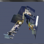
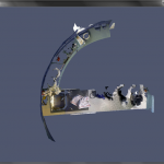
Scanoman and Vali saying bye-bye
And, yes, you need a more than decent computer, but not necessarily a top edge one. I’m using an Acer Aspire V3 which works very well and its price tag is well below 1000 EUR.
When it comes to money, if we put aside the sensor, Scanoman cost would be below 250 EUR, including all materials, electronics, motors, etc. Well, it will take some time to build one, but this is fun, lots of fun! And, as promised, Scanoman is open source.
Coming up next is a new version of Scanoman. It will focus on optimizing the construction, reducing weight and improving usage. Then more thoughts should be given to performance and quality.
You may want to keep an eye on that, by following 3Dmaker4U on the website, Facebook, YouTubeor LinkedIn.
3Dmaker4U is an initiative that is aimed to promoting and developing 3D technologies, such as 3D printing, 3D scanning and 3D modelling, and their applications.
Bye-bye for now and enjoy the short Scanoman introductory video below!